Each symbol must represent the specific function of the switch and must be set up for plan view visibility. Symbols can be created using symbolic lines, annotation elements, or reference components depending on the detail level. Here’s how to organize these:
Single Pole Switch Symbol:
- Simple “S” symbol for single switch.
- This is a 2D annotation visible in plan views.
Three-Way Switch Symbol:
- Typically represented with “3” or “S3” inside the switch symbol.
- Similarly to the single-pole symbol but with clear differentiation using annotation.
Four-Way Switch Symbol:
- Symbol can show “4” or “S4” to indicate four-way functionality.
Dimmer Switch Symbol:
- Use a stylized “D” or curve symbol to differentiate the dimmer.
Timer Switch Symbol:
- Symbol can be represented with a “T” or clock-like design to signify the timer function.
3D Model:
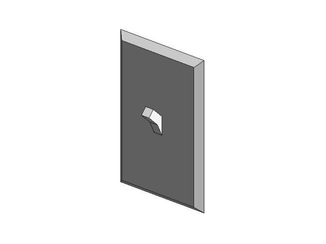
- Symbols are shown in plan view has a 3D representation for placement in model views.
Parameters for Type Variants:
- Type Parameters for each switch type (Single, Three-Way, Four-Way, Dimmer, Timer). Use these to control the display of the symbols. When a user selects a type, the corresponding symbol will show up in plan views. You can control this by using visibility settings or sub-categories for each symbol.
Connector Setup:
- Add electrical connectors with proper voltage and power rating to connect these switches into circuits. Define different connector settings for each type (e.g., single pole might only have one connection, while three-way and four-way might have multiple).
Visibility Settings:
- Use visibility controls in the family editor to ensure that only one symbol (Single, Three-Way, Four-Way, Dimmer, Timer) is visible at a time based on the selected family type or parameter.
Light Switch Multiple Use.rfa
728 KB

